LED Behavior Matrix
This page explains the behavior and purpose of each LED indicator on the OV20i camera, based on color and function.
note
Use this as a quick visual reference during setup, inspection, and troubleshooting.
LED Locations & Meanings
The OV20i includes 4 LED indicators on the top panel of the device, each with a distinct purpose:
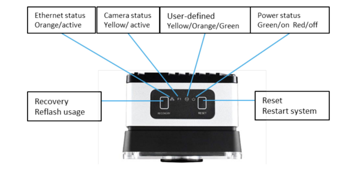
| LED Label | Color | Function |
|---|---|---|
| Ethernet Status | 🟠 Orange (Active) | Indicates network link or activity |
| Camera Status | 🟡 Yellow (Active) | Indicates image capture or streaming state |
| User-defined | 🟡/🟠/🟢 Yellow, Orange, Green | Reserved for software-defined behaviors |
| Power Status | 🟢 Green (On) / 🔴 Red (Off) | Indicates system power and health status |
Button Functions
| Button | Function | Notes |
|---|---|---|
| Recovery | Reflash usage (Support only) | Not to be used by customers |
| Reset | Restart system (Safe reboot) | Use if camera is unresponsive |
LED Quick Reference Table
| LED | State | What It Means |
|---|---|---|
| Ethernet (🟠) | Solid or blinking | Network link present and active |
| Camera (🟡) | Solid or blinking | Camera is running or capturing images |
| User-defined | Varies (🟢🟡🟠) | Reserved for internal diagnostics or software mapping |
| Power (🟢/🔴) | Green = On | System is powered and operational |
| Red = Off | No power detected (check power input and cable) |
Field Usage Notes
- Ethernet LED not lit? → Check cable seating, switch status, or static IP conflict
- Power LED red/off? → Confirm 24 VDC input and M12 connector seating
- Camera LED off during trigger? → Make sure camera is in hardware trigger mode
- User-defined LED stays orange? → May indicate fallback or non-ready state